

SEARCH
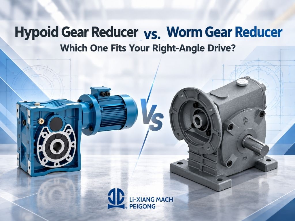
Hypoid Gear Reducer vs. Worm Gear Reducer: Which One Fits Your Right-Angle Drive?
When a machine requires power to change direction by 90 degrees, both a hypoid gear reducer and a worm gear reducer may appear to be suitable solutions.
However, choosing between them should not be based on installation direction alone.
The two reducer types transmit power through different gear geometries, which affects efficiency, heat generation, reduction ratio, back-driving characteristics, operating duty, and long-term system performance.
For a conveyor that runs continuously for many hours, energy efficiency may be one of the main considerations. For a lifting or positioning mechanism, resistance to reverse movement may be more important. Other machinery may require a very large reduction ratio within limited installation space.
At PEIGONG, both hypoid and worm gear reducers are available for industrial power transmission applications. The important question is therefore not simply which reducer is “better,” but which transmission principle better matches the actual operating requirements of the machine.
This article compares hypoid gear reducers and worm gear reducers from an application perspective and explains the factors engineers should evaluate before choosing a right-angle drive solution.
Table of Contents
- Quick Comparison: Hypoid vs. Worm Gear Reducer
- What Is a Right-Angle Gear Reducer?
- How Does a Hypoid Gear Reducer Work?
- How Does a Worm Gear Reducer Work?
- Hypoid Gear Reducer vs. Worm Gear Reducer: Key Differences
- Efficiency and Heat Generation
- Reduction Ratio Requirements
- Back-Driving and Self-Locking Requirements
- Continuous-Duty Operation
- Compact Installation Space
- Which Applications Are Better for Hypoid Gear Reducers?
- Which Applications Are Better for Worm Gear Reducers?
- How to Choose Between a Hypoid and Worm Gear Reducer
- Hypoid or Worm? A Practical Selection Guide
- PEIGONG Right-Angle Gear Reducer Solutions
- Related Reading
- Conclusion
Quick Comparison: Hypoid vs. Worm Gear Reducer
Before looking at each factor in detail, the basic selection logic can be summarized as follows:
| Selection Factor | Hypoid Gear Reducer | Worm Gear Reducer |
|---|---|---|
| Transmission Direction | Right-angle transmission | Right-angle transmission |
| Efficiency Priority | Generally better suited when reducing power loss is important | More sliding contact can result in greater power loss |
| Continuous Operation | Strong option for long-duty operation where efficiency matters | Suitable when correctly sized, but thermal conditions require greater attention |
| High Reduction Ratio | Suitable for moderate reduction ratios depending on model | Particularly useful when large reduction ratios are required |
| Back-Driving Resistance | Normally not selected primarily for self-locking | Certain worm configurations can provide resistance to back-driving |
| Compact Installation | Compact right-angle configuration | Compact right-angle configuration |
| Typical Selection Priority | Efficiency, continuous duty, compact power transmission | High reduction ratio, smooth transmission, load-holding characteristics |
The correct choice still depends on motor speed, required output speed, torque, duty cycle, mounting arrangement, operating environment, and safety requirements.
What Is a Right-Angle Gear Reducer?
A right-angle gear reducer changes the direction of power transmission so that the input shaft and output shaft are arranged approximately 90 degrees from one another.
This layout is useful when placing the motor directly in line with the driven equipment would require too much installation space or interfere with surrounding machine components.
Right-angle reducers are therefore commonly found in:
- Conveyor systems
- Packaging equipment
- Material handling machinery
- Automated production equipment
- Lifting and positioning mechanisms
- Metalworking machinery
- Assembly lines
Both hypoid and worm gear mechanisms can create a compact right-angle transmission, but the way they transfer torque is fundamentally different.
That difference becomes important when evaluating real-world performance.
How Does a Hypoid Gear Reducer Work?
A hypoid gear set uses specially shaped gears with axes that do not intersect directly. The pinion axis is offset from the centerline of the mating gear.
This offset allows multiple teeth to remain in contact during transmission while providing a compact right-angle arrangement.
Compared with a conventional worm drive, a hypoid transmission generally involves more rolling action and less extreme sliding contact. This characteristic can help reduce power losses and improve transmission efficiency.
PEIGONG describes its HYPOID Gear Reducer as a compact transmission solution designed for high performance, low power loss, and industrial applications including automotive assembly, metalworking, and packaging.
For example, PEIGONG's AH..B 50 is offered with reduction ratios from 7.5 to 60, illustrating the type of moderate-ratio application in which hypoid transmission can be considered.
How Does a Worm Gear Reducer Work?
A worm gear reducer normally consists of a screw-like worm that drives a worm wheel.
The axes of the worm and worm wheel are positioned at approximately 90 degrees, making the system naturally suited to right-angle power transmission.
Unlike a hypoid drive, worm gearing relies heavily on sliding contact between the mating surfaces.
This sliding action gives the worm reducer several useful characteristics, including smooth transmission and the ability to achieve substantial speed reduction.
PEIGONG's Worm Gear Reducer range uses a worm, worm wheel, and output shaft and is available in numerous configurations for different industrial installation requirements.
PEIGONG also highlights compact construction, smooth operation, high torque at low speed, and self-locking characteristics within its worm reducer product range.
One important advantage is the range of ratios available.
For example, PEIGONG's PBE series covers ratios from approximately 5 to 60, while other worm reducer configurations can provide considerably higher reduction ranges depending on the selected model and arrangement.
Hypoid Gear Reducer vs. Worm Gear Reducer: Key Differences
The main difference is not simply the shape of the gears.
It is how power moves through the gearbox.
A worm drive depends substantially on sliding friction between the worm and worm wheel. A hypoid drive combines sliding and rolling contact with a different gear geometry.
As a result, the two reducers behave differently when engineers begin evaluating:
- Power loss
- Temperature rise
- Continuous operation
- Reduction ratio
- Reverse driving
- Required motor power
- Duty cycle
This is why replacing one reducer type with another based only on mounting dimensions or ratio can produce unexpected machine behavior.
1. Efficiency and Heat Generation
Efficiency is one of the clearest reasons engineers may consider a hypoid gear reducer.
Because worm gears rely heavily on sliding contact, part of the input energy is converted into frictional heat rather than useful output power.
As load and operating time increase, thermal behavior becomes increasingly important.
A hypoid transmission can generally reduce these sliding-related losses compared with a conventional worm drive. PEIGONG specifically positions its hypoid reducer around high transmission efficiency and low power loss.
This difference can matter in machinery that:
- Runs for long periods
- Uses several gear motors
- Operates under significant load
- Has limited heat dissipation
- Requires lower overall energy consumption
Example
Consider two conveyors that require the same output speed.
One operates only periodically during a production shift. The other runs almost continuously.
Although both may be able to use a worm reducer, the continuous-duty conveyor places greater importance on energy loss and gearbox temperature. In such a situation, evaluating a hypoid reducer may provide greater long-term operating value.
2. Reduction Ratio Requirements
Efficiency alone does not determine reducer selection.
The required ratio may immediately change the decision.
The theoretical reduction ratio can be estimated from:
For example, if:
- Motor speed = 1,500 rpm
- Required output speed = 50 rpm
The required ratio is approximately:
A 30:1 application can potentially fall within the range of both hypoid and worm reducer configurations.
But consider another machine requiring an extremely slow output speed.
As the required ratio becomes much larger, worm gearing—or a multi-stage worm arrangement—can become particularly useful.
PEIGONG illustrates this distinction well. Its AH..B 50 hypoid reducer lists ratios between 7.5 and 60, while certain worm reducer families offer substantially larger ratios through different configurations.
3. Back-Driving and Self-Locking Requirements
This is another area where worm gear reducers require special attention.
Depending on worm geometry, lead angle, friction conditions, lubrication, and loading, a worm drive can offer substantial resistance to reverse rotation.
PEIGONG identifies self-locking behavior as one of the characteristics of its worm gear reducer range.
This can be relevant for equipment such as:
- Lifting mechanisms
- Vertical positioning systems
- Adjustment devices
- Material handling equipment
- Applications where reverse movement is undesirable
However, an important engineering distinction must be made:
Whether a worm gear can back-drive depends on the actual reducer design and operating conditions. Applications involving suspended loads or personnel safety may still require dedicated braking or holding systems.
A hypoid gear reducer, by comparison, is normally selected for efficient torque transmission rather than self-locking behavior.
4. Continuous-Duty Operation
Duty cycle describes how frequently and how long the machine operates.
It should not be ignored when comparing gearbox types.
A gearbox that runs for several minutes every hour experiences very different thermal conditions from one that operates continuously for an entire production shift.
For continuous-duty machinery, power loss becomes heat.
This makes efficiency, lubrication, ambient temperature, gearbox size, and actual transmitted torque important parts of the selection process.
Because a hypoid gear reducer can provide efficient right-angle transmission with comparatively low power loss, it can be particularly attractive for continuous-running industrial equipment.
Typical examples include:
- Conveyor lines
- Packaging machinery
- Automated manufacturing systems
- Automotive assembly equipment
- Production machinery
Worm gear reducers can also operate reliably in industrial duty, but their thermal capacity must be evaluated rather than assuming that a gearbox is suitable simply because its mechanical torque rating appears sufficient.
5. Compact Installation Space
Both designs can solve an important mechanical engineering problem:
This makes both reducers useful in compact machinery.
PEIGONG specifically describes its hypoid reducer as having a compact design, while its worm reducer line also provides compact power transmission configurations.
However, “compact” should not simply mean choosing the physically smallest reducer.
Engineers should also check:
- Output shaft orientation
- Motor mounting direction
- Service access
- Lubrication requirements
- Surrounding machine structure
- Required torque capacity
- Thermal dissipation
A smaller reducer installed in an enclosed area may not necessarily be the best solution if heat cannot dissipate effectively.
Which Applications Are Better for Hypoid Gear Reducers?
A hypoid gear reducer becomes particularly attractive when the application requires a combination of:
Right-angle transmission + compact design + continuous operation + efficient power transfer.
Conveyors
Continuous conveyor systems can benefit from reduced transmission losses, particularly where several geared motors operate simultaneously.
Packaging Machinery
Packaging equipment often combines long operating hours with limited installation space, making compact and efficient drive systems valuable.
Automotive Assembly
Automated assembly lines frequently require reliable continuous power transmission across multiple drive axes.
Metalworking Equipment
Machines operating under repeated or substantial loads may benefit from efficient torque transmission and robust gearbox construction.
Which Applications Are Better for Worm Gear Reducers?
A worm gear reducer remains highly useful when the application places greater emphasis on:
Large reduction ratios, smooth transmission, compact right-angle layout, or resistance to reverse motion.
Lifting Equipment
Where controlled movement and resistance to back-driving are important, worm transmission characteristics may provide an advantage.
Positioning Mechanisms
Slow, controlled adjustment mechanisms can benefit from high reduction ratios.
Material Handling Equipment
Worm reducers can provide low-speed, high-torque output in a compact layout.
Conventional Industrial Machinery
Worm gearing has been widely used across many types of machinery because of its simple right-angle transmission arrangement and broad selection of ratios and configurations.
How to Choose Between a Hypoid and Worm Gear Reducer
Instead of beginning with the gearbox type, begin with the machine requirements.
Step 1: Determine the Required Output Speed
Calculate the required reduction ratio from motor speed and target output speed.
This immediately helps identify which reducer configurations are practical.
Step 2: Calculate the Required Torque
Do not select a reducer based only on nominal motor power.
Consider:
- Continuous torque
- Starting torque
- Peak torque
- Acceleration and deceleration
- Shock loads
Insufficient torque capacity can lead to premature wear or gearbox failure regardless of the gear type.
Step 3: Evaluate Operating Time
Ask:
- Does the machine operate intermittently?
- Several hours per shift?
- Almost continuously?
The longer the operating time, the more important efficiency and thermal performance become.
Step 4: Determine Whether Back-Driving Matters
If the driven load can cause the gearbox output shaft to rotate backward, determine whether reverse movement is acceptable.
If load holding is important, worm gearing may deserve closer evaluation.
If the application is safety-critical, a separate braking solution should also be considered.
Step 5: Evaluate Installation Space
Check more than external dimensions.
Confirm:
- Input orientation
- Output shaft direction
- Motor position
- Mounting style
- Maintenance access
PEIGONG's worm reducer range, for example, includes numerous output-direction arrangements, allowing greater flexibility when integrating a reducer into existing machinery.
Step 6: Compare Lifetime Operating Requirements
The gearbox with the lower initial purchase price is not necessarily the lower-cost transmission solution over the life of the machine.
For equipment operating many hours per day, engineers should also consider:
- Energy consumption
- Heat generation
- Lubrication
- Maintenance
- Production downtime
- Expected service life
This is where the efficiency advantage of hypoid gearing can become particularly relevant.
Hypoid or Worm? A Practical Selection Guide
Consider a Hypoid Gear Reducer When:
- The machine requires a 90-degree drivetrain.
- Energy efficiency is important.
- The equipment operates for long periods.
- Reducing power loss and thermal load is a priority.
- The required ratio falls within the available hypoid range.
- Compact installation is necessary.
Consider a Worm Gear Reducer When:
- The machine requires a large speed reduction.
- Back-driving resistance is important.
- Smooth low-speed transmission is required.
- A wide range of ratios or shaft arrangements is needed.
- The machine already uses a conventional worm-drive architecture.
There will naturally be applications where either solution could work.
In these cases, the final decision should be based on the complete drivetrain, not a single gearbox specification.
PEIGONG Right-Angle Gear Reducer Solutions
PEIGONG manufactures power transmission solutions for industrial machinery, with its product portfolio including worm gear reducers, helical gear reducers, planetary gear reducers, gear motors, screw jacks, miter reducers, hypoid reducers, and other transmission products.
For right-angle drive applications, both HYPOID Gear Reducers and Worm Gear Reducers provide viable solutions, but they serve different engineering priorities.
A customer selecting a reducer should therefore provide more than the required ratio.
Useful information includes:
- Motor power
- Motor speed
- Required output speed
- Continuous torque
- Peak torque
- Operating hours
- Starting frequency
- Load characteristics
- Mounting orientation
- Installation space
- Environmental conditions
- Back-driving or load-holding requirements
Evaluating these factors together allows the reducer to be matched more closely to the actual machine rather than selected from a single catalog value.
Related Reading
If you are evaluating gear reducers for different operating conditions, these related guides provide additional information on reducer selection, continuous-duty operation, and load-holding requirements.
How to Select the Best Bevel Gear Reducer for Continuous-Duty Applications
Learn how torque capacity, reduction ratio, thermal performance, lubrication, gear quality, and operating environment should be evaluated when selecting a reducer for machinery that operates for extended periods.
Common Worm Gear Reducer Selection Mistakes and How to Avoid Them
Review common mistakes involving reduction ratio, output torque, duty cycle, self-locking requirements, mounting position, and operating conditions before choosing a worm gear reducer.
How Worm Gear Linear Actuators Improve Load Holding in Vertical Applications
Explore how worm gear transmission characteristics can help resist back-driving and support stable load positioning in vertical lifting and adjustment applications.
Conclusion
There is no universal winner in the hypoid gear reducer vs. worm gear reducer comparison.
Both provide compact right-angle power transmission, but they solve different engineering priorities.
A hypoid gear reducer is particularly attractive when high transmission efficiency, lower power loss, compact installation, and continuous operation are important.
A worm gear reducer, meanwhile, remains valuable when high reduction ratios, flexible configurations, smooth transmission, and resistance to reverse movement are key requirements.
The most important decision is therefore not:
It is:
By evaluating the complete operating conditions before selecting the reducer, machinery manufacturers can achieve a better balance of performance, efficiency, reliability, and long-term operating cost.
Not sure whether a hypoid or worm gear reducer is better for your right-angle drive? Contact PEIGONG with your motor power, speed, required ratio, torque, operating time, and installation requirements. Our team can help you evaluate a suitable power transmission solution for your machinery.